Concept
The basic concept of Hydrocyclone is to separate solids, liquids from mixture of Solid-liquid, liquid-liquid simultaneously. The separation is depending on the Density and particle size of the Solids.
Working principle
The Separation action of hydrocyclones is based on the effect of Centrifugal forces created within the cyclone body. In contrast to sedimenting centrifuges, however, hydrocyclones have no rotating parts and the necessary vortex is produced by pumping the fluid tangentially into a stationary cono-cylindrical body.
In principle, however, each hydrocyclones separates particles of the dispersed phase (usually heavy) from the liquid (continuous phase) on the basis of density difference between the phases and the separation depends heavily on particle size. The selection is made on the basis of required flow capacity Q and a given particle size (micron).
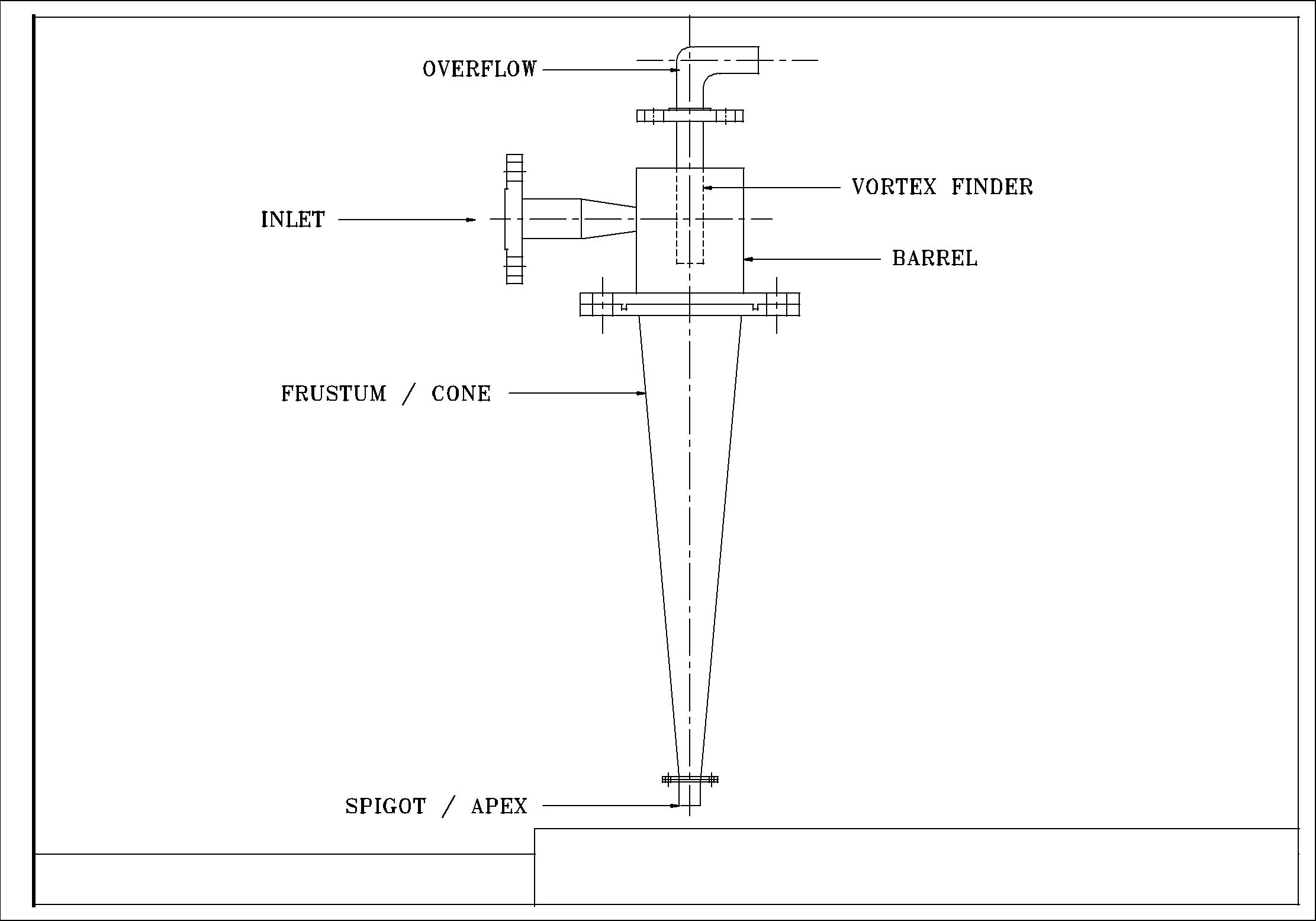
Parts of Hydrocyclone
- Inlet
- Overflow
- Barrel
- Frustum/Cone
- Apex/Spigot.
- Vortex finder
Applications
- Recovery of Catalyst in the oil and chemical industries.
- Separation of sand from sugar cane juice.
- Removal of silt from well water
- Separation of corrosion products in circulating systems in the nuclear power industry.
- Clean-up of wash water from gas scrubbers for recycling
- Clean-up of water in car wash system.
- Pre-cleaning of primary sewage sludge (1 to 2%).
- Clarification of seed oil.
- Dewatering of mine backfill.
- De-sliming of minerals prior to flotation; this allows easier flotation and requires the use of less reagent.
- Removal of impurities and ungrounded particles from chalk.
- Recovery of filter aid.
- De-sliming of phosphate rock.
Advantages
- No Moving parts in the Hydrocyclone make the installation simpler
- Lower capital cost
- Can be used in Hazardous environment.
- No Maintenance.
Design Standard
- ASME B31.3
- ASME B16.5
- ASME B16.47
- ASME SEC VIII DIV I
- ASME SEC VI DIV A/B/C
Hydrocyclone Design Calculations
Method Based on Bradley (1965) & Rietema (1961) research work:
- Assume Pressure Drop (ΔP)(N/M2)
- Constant (Np, Kp, Stk50.Eu) as per respective Scientist.
- Calculate Hydrocyclone Diameter.
- Calculate inlet Diameter
- Calculate Overflow Diameter
- Calculate Length of Vortex finder
- Calculate Total Length of Cyclone
| Constant | Bradley | Reitema |
|---|---|---|
| Kp | 446.5 | 316 |
| Np | 0.323 | 0.314 |
| Stk50.Eu | 0.1111 | 0.0611 |
D(4+Np) = ( 4Q/Π )(2+Np) (ρ/μ)Np (Kp.ρ/2ΔP)
Where,
D= Diameter of Hydrocyclone (m)
Q= Flow rate (m3/s)
ρ= Liquid density (kg/m3)
µ= Liquid Viscosity (Ns/m2)
Stk50.Eu= Constant (Unitless)
| Bradley | Reitema | |
|---|---|---|
| Di/D | 0.133 | 0.28 |
Where Di = Internal Diameter
D = Hydrocyclone Diameter
| Bradley | Reitema | |
|---|---|---|
| Do/D | 0.20 | 0.34 |
Do = Overflow Diameter
| Bradley | Reitema | |
|---|---|---|
| l/D | 0.33 | 0.0.4 |
Where l = Length of Vortex finder.
| Bradley | Reitema | |
|---|---|---|
| L/D | 6.85 | 5 |
Where L = Total length of Hydrocyclone.
Next step is to calculate the particle Cut size by using the below mentioned formula.
X2 50 = (Stk50.Eu x 36 x Ρ x µ x Q) / (π x ΔP x Δρ x D)
The above described trial and error can be avoided by substitution of Q/N for Q in both equations above, and their simultaneous solution for cyclone diameter D and number of cyclones in parallel N.
Material of Construction
- Carbon Steel
- Carbon Steel + FRP
- Carbon Steel + PVC
- Carbon Steel + Rubber Lined
- Carbon Steel + Epoxy Coating
- Stainless Steel ( SS 304,SS 304L,SS 316,SS 316L)